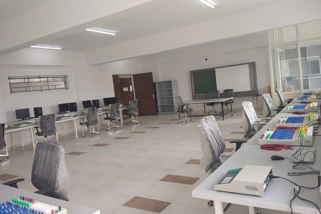
Control Systems Lab, Digital Signal Processing Laboratory
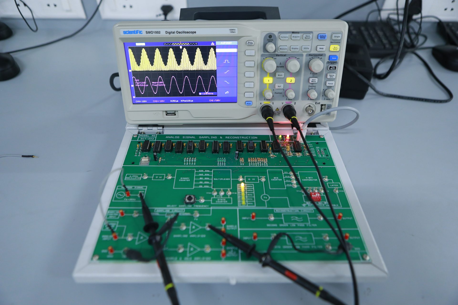
Digital Signal Processing Laboratory
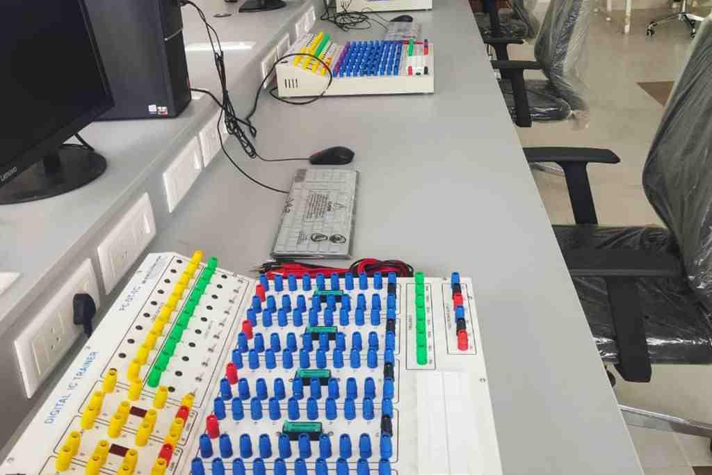
Analogue and Digital Electronics Lab
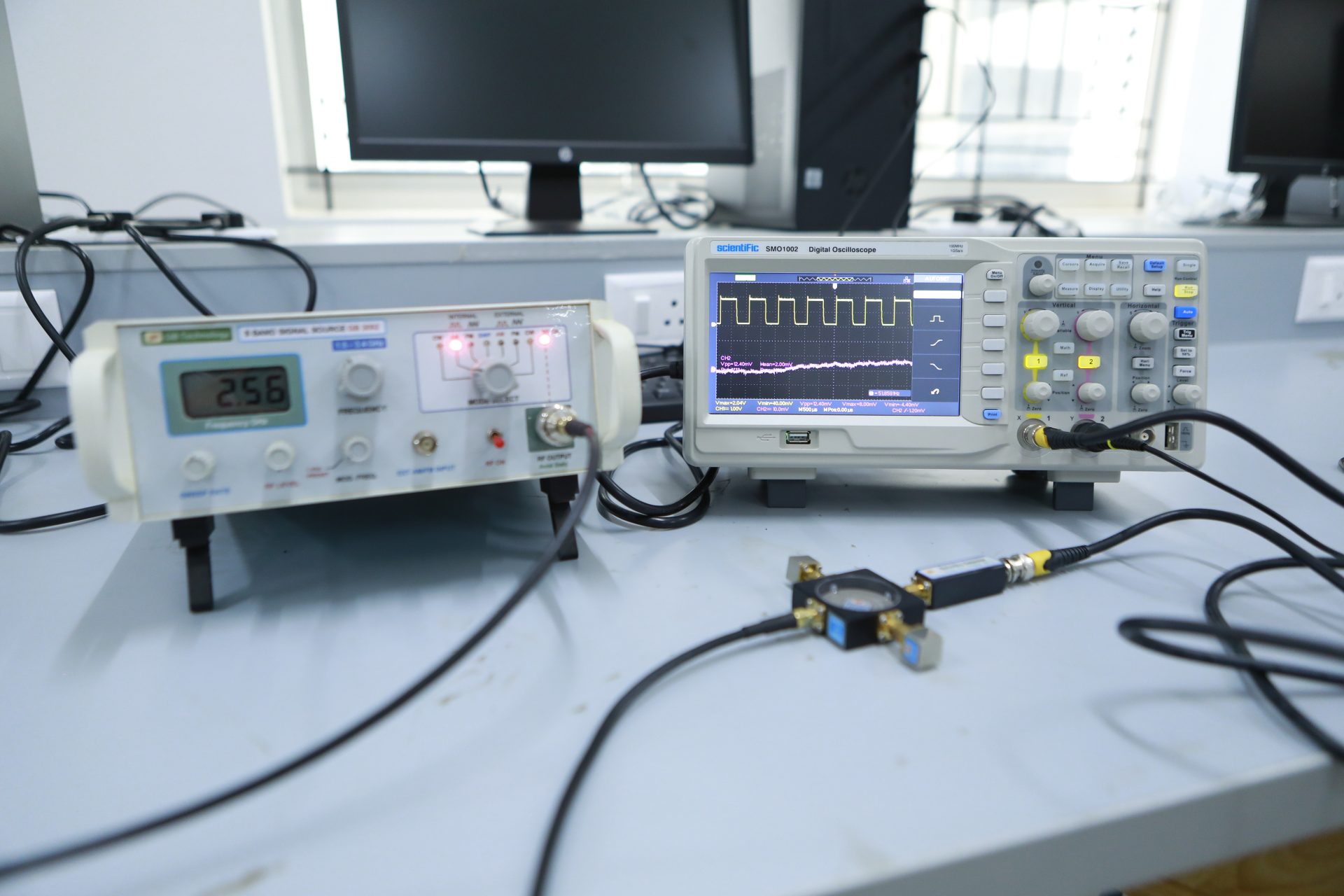
Communication Lab
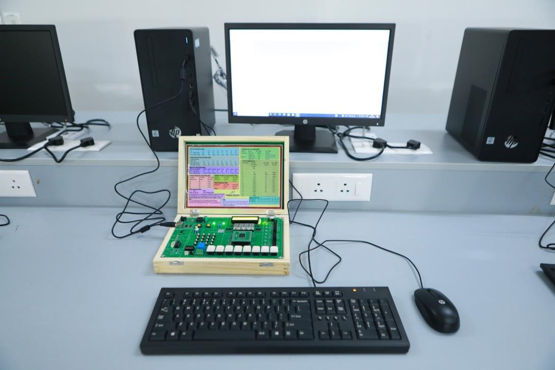
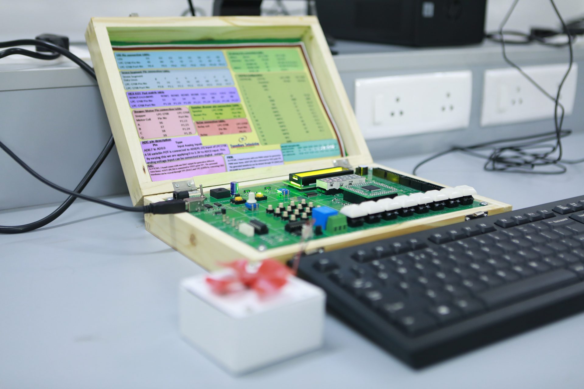
Microcontroller Laboratory
VLSI Laboratory
Digital System Design Using Verilog
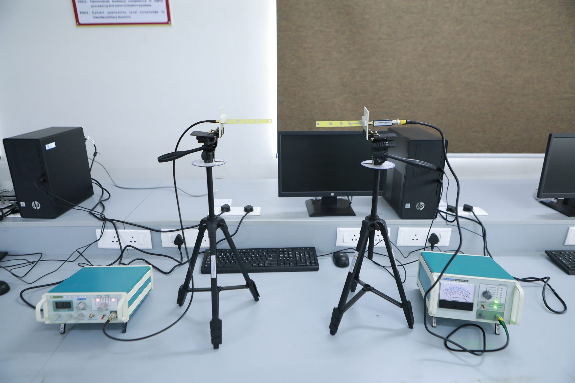
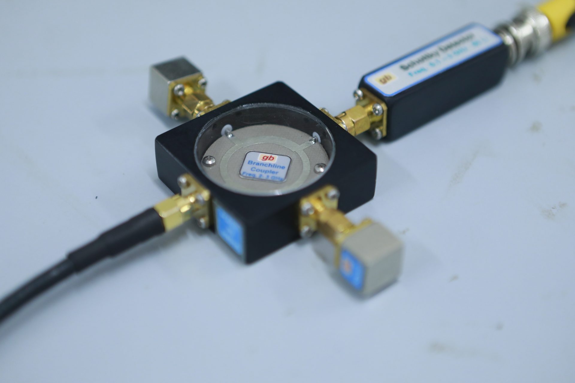
Microwave Theory and Antennas Laboratory