Subject Code : BCEDK103 / BCEDK203
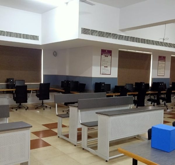
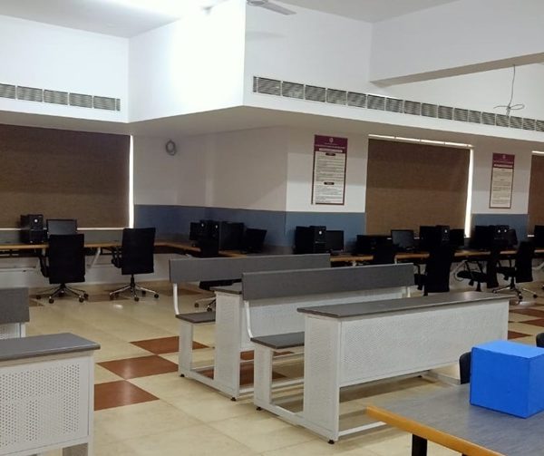
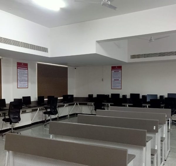
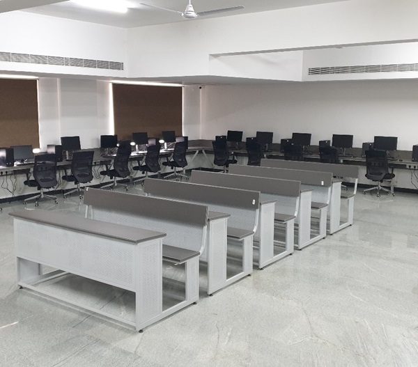
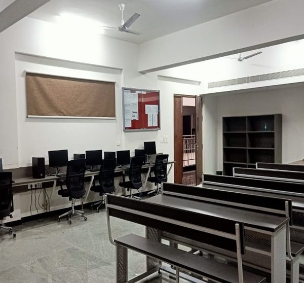
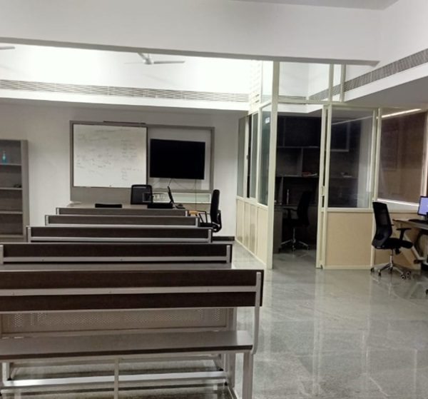
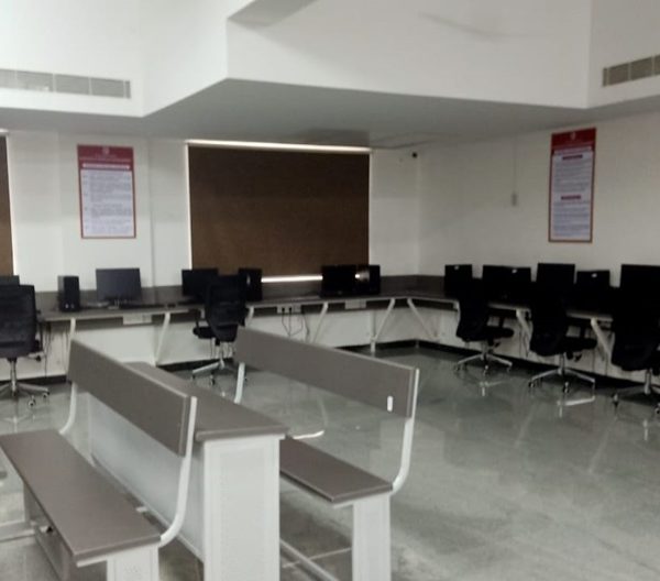
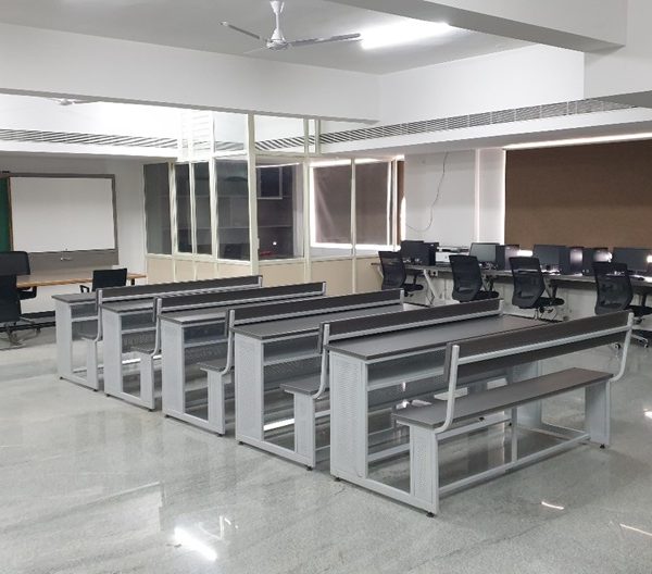
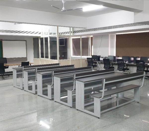
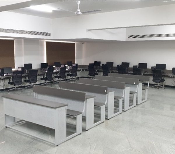
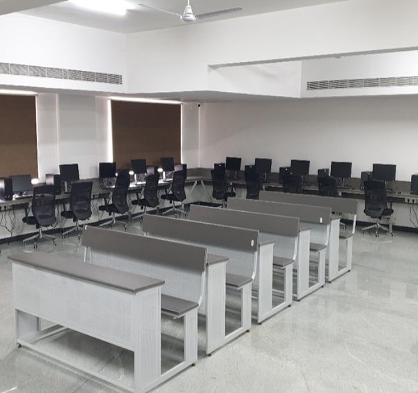
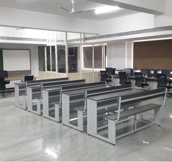
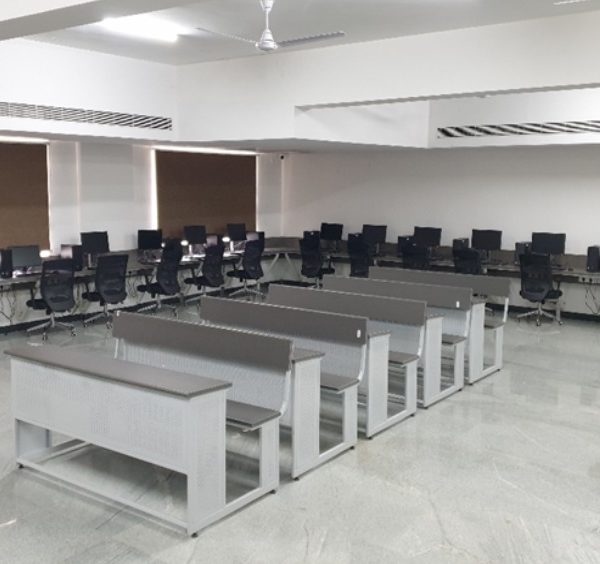
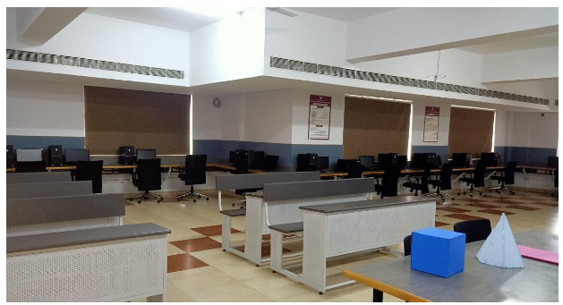
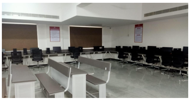
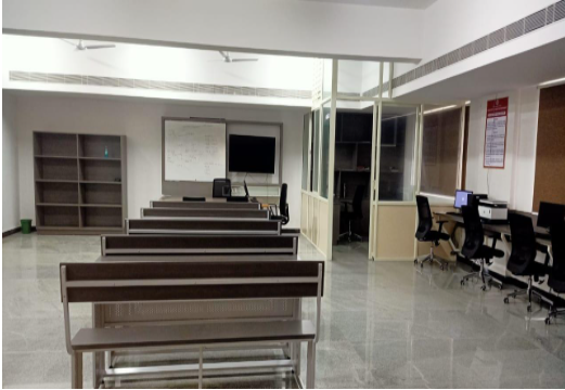
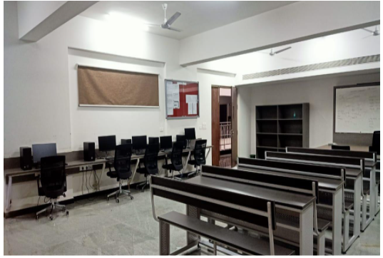
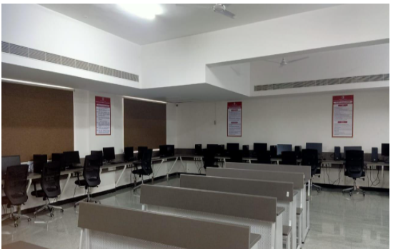
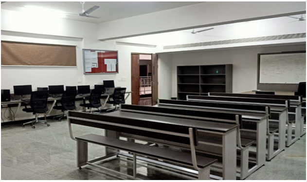
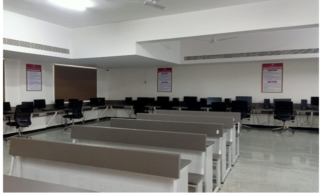
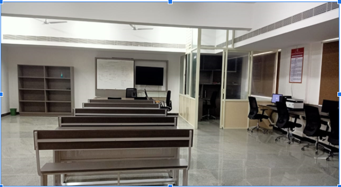
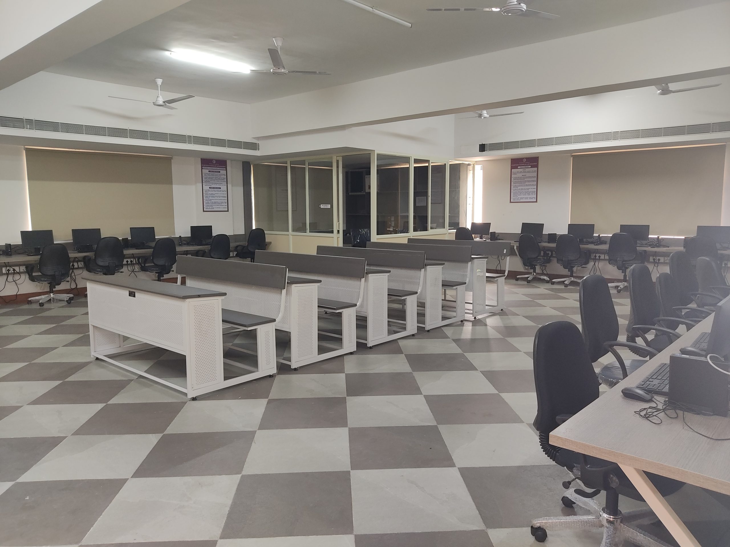
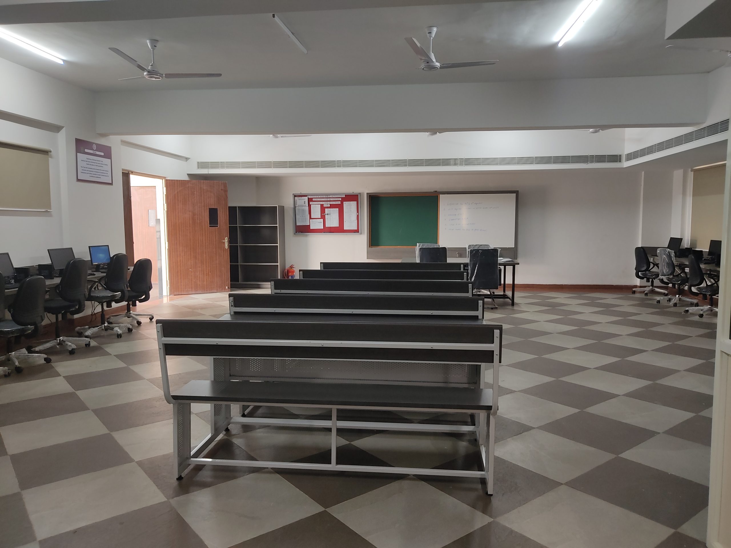
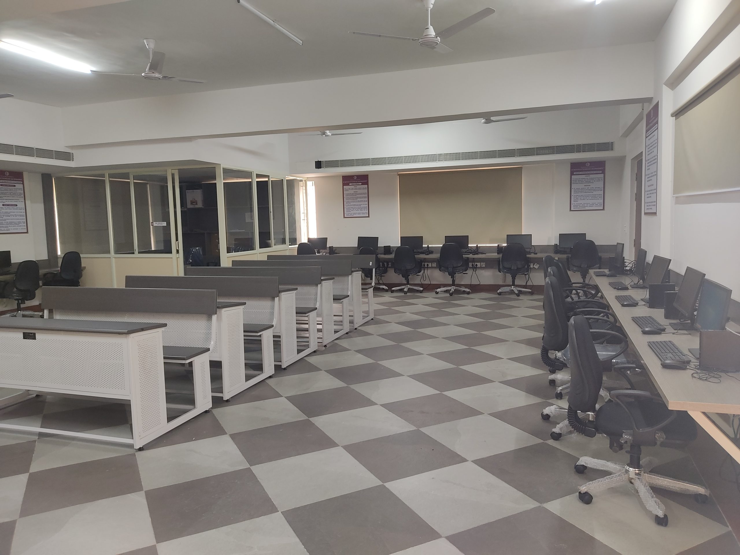
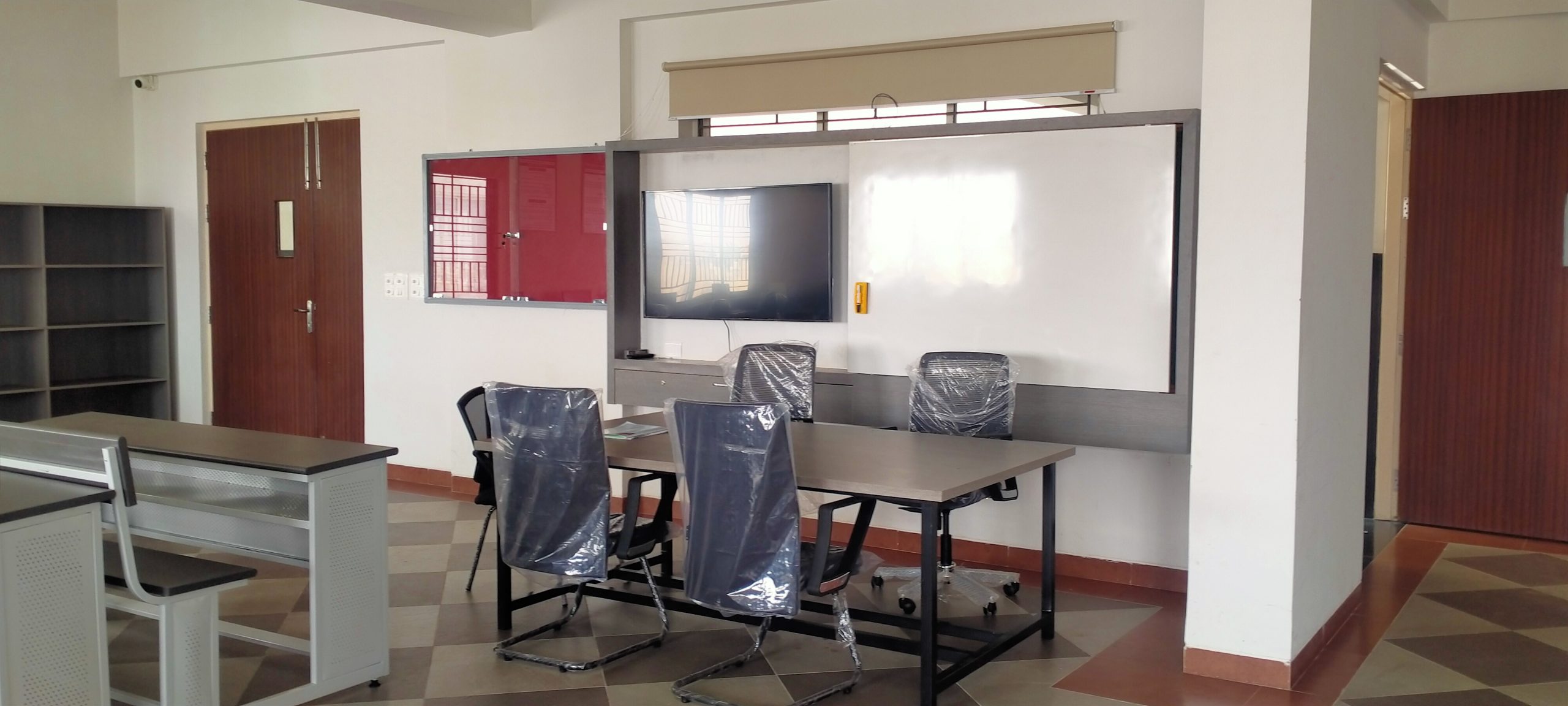
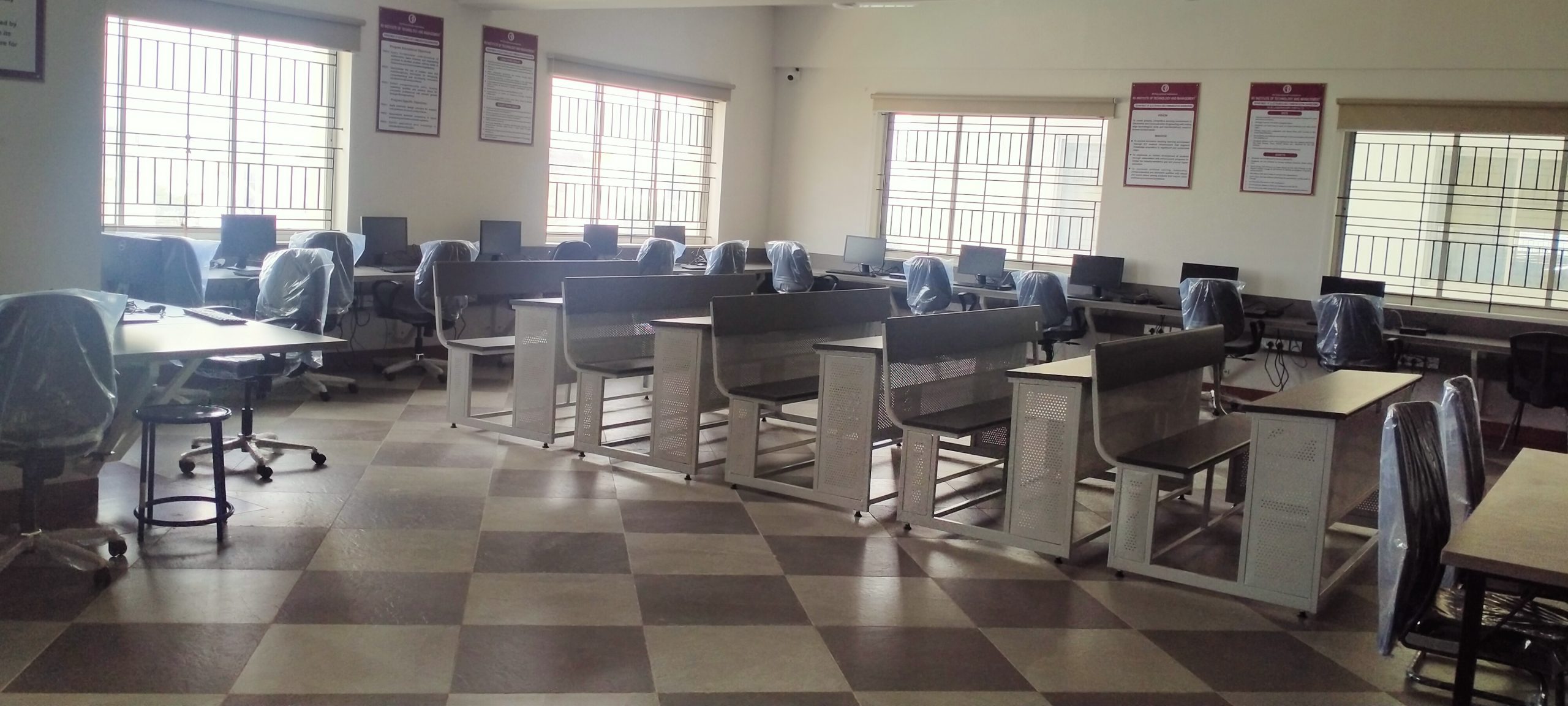
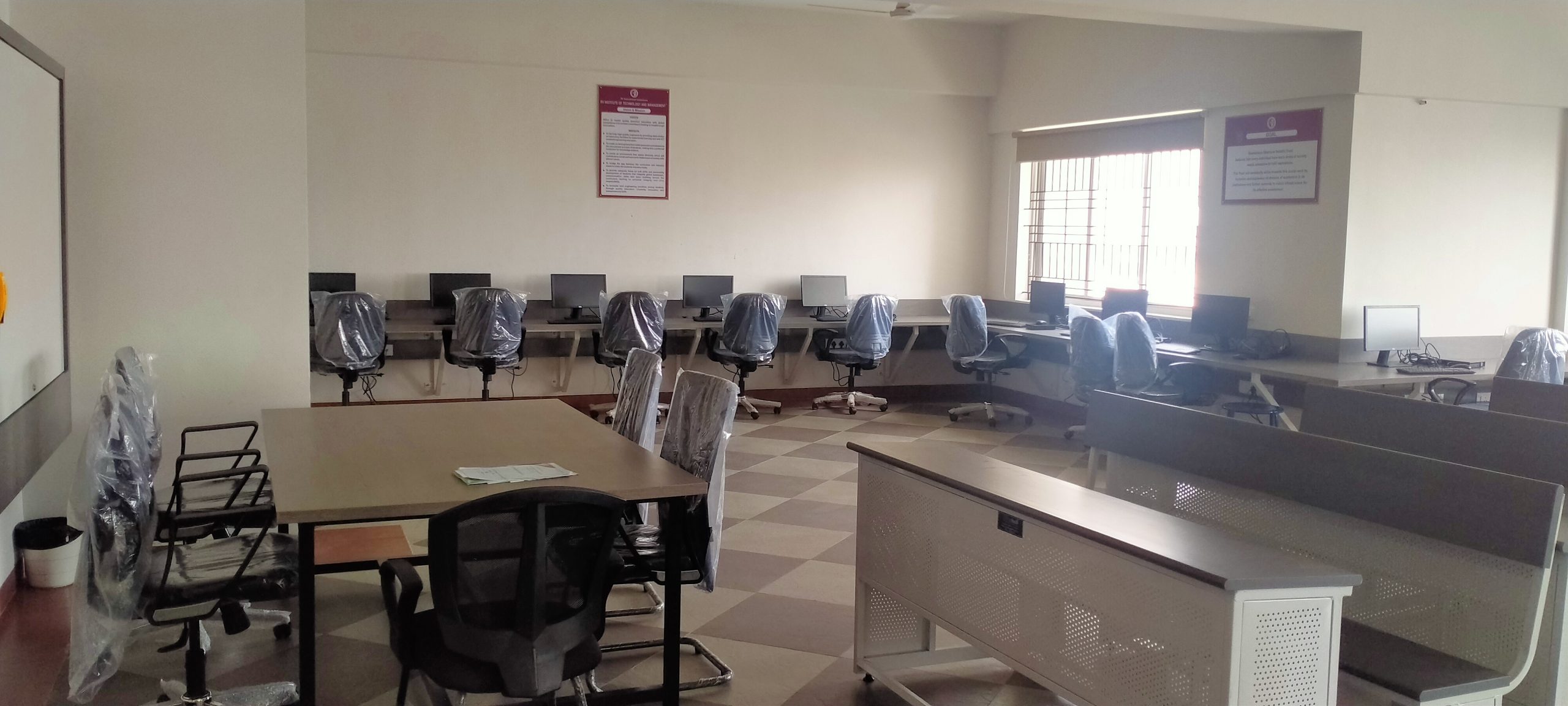
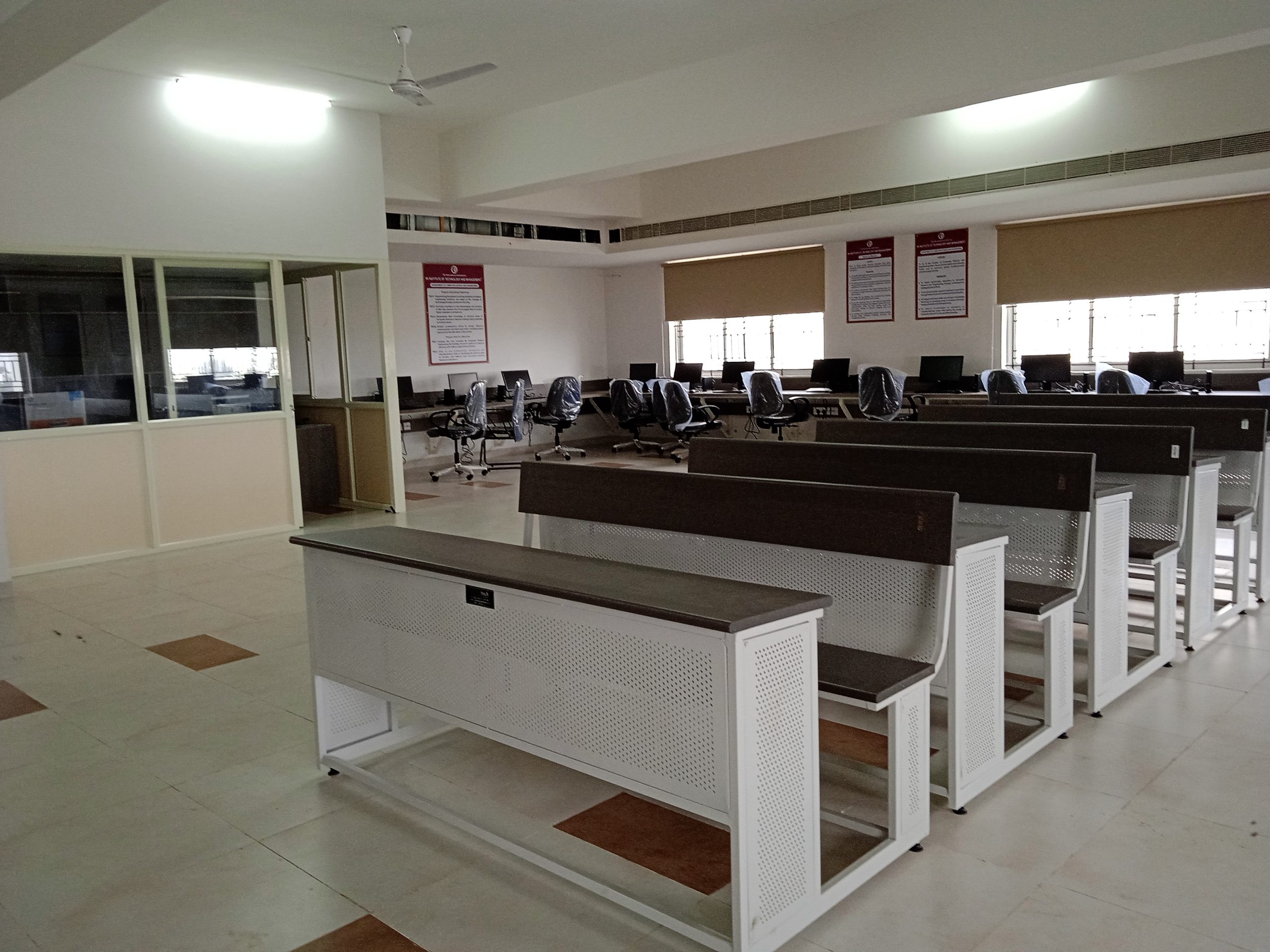
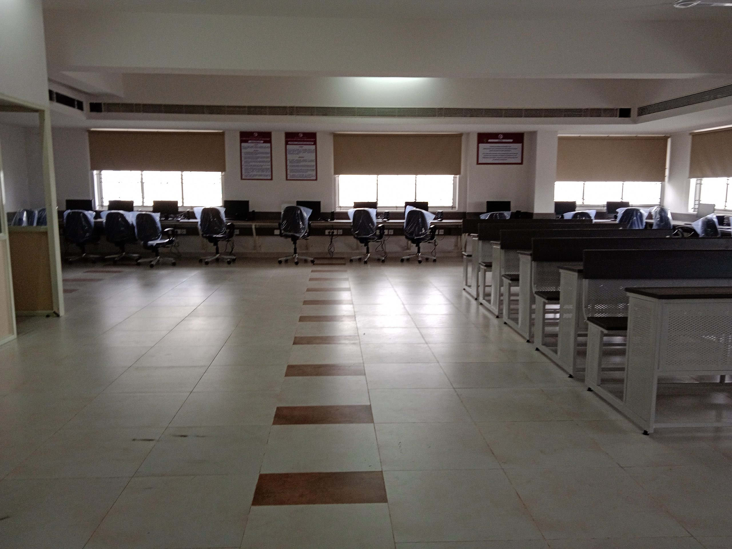
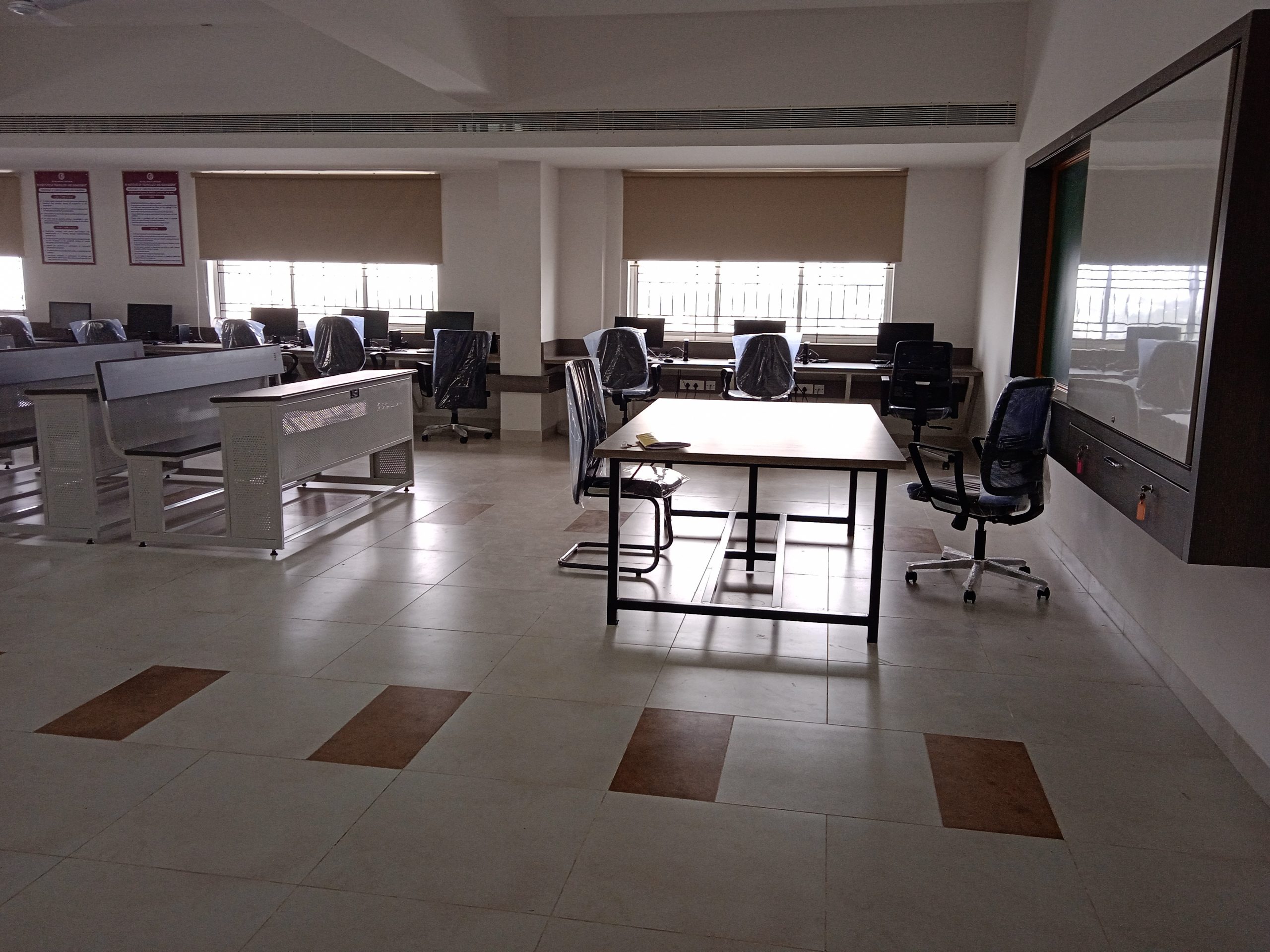
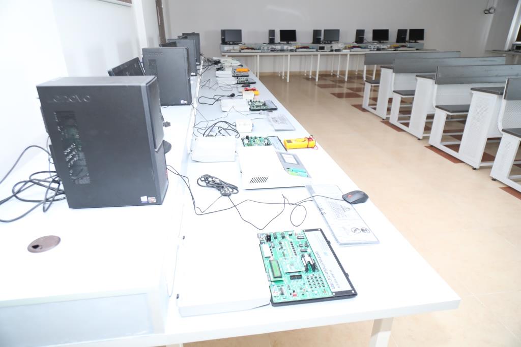
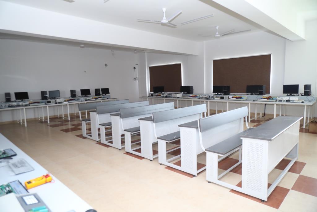
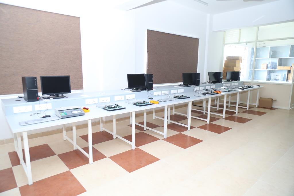
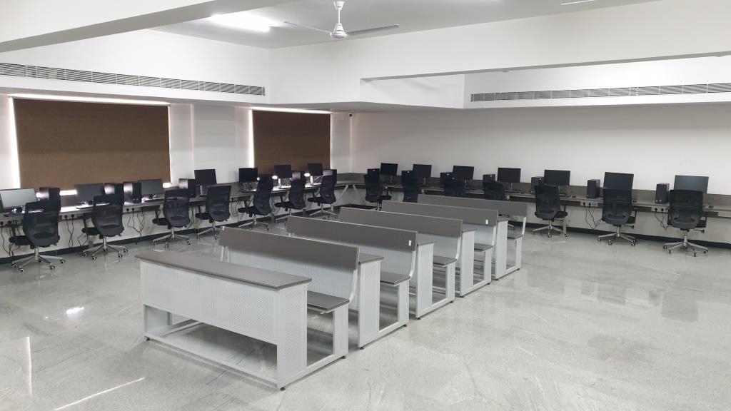
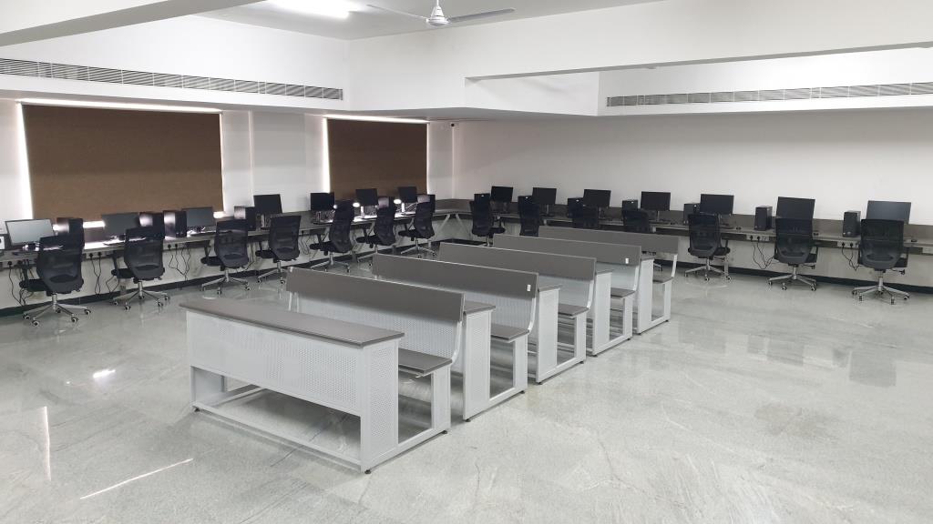
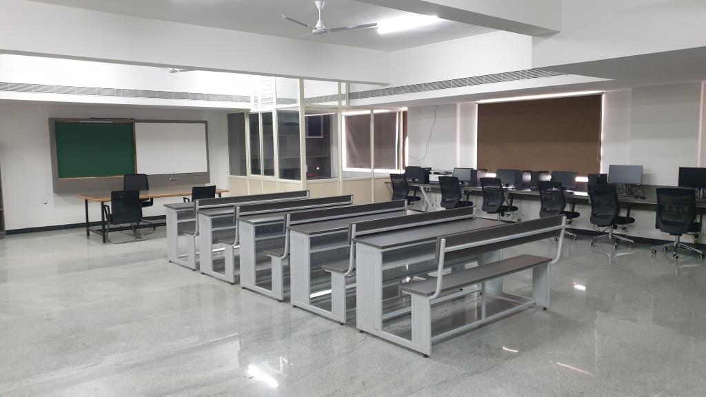
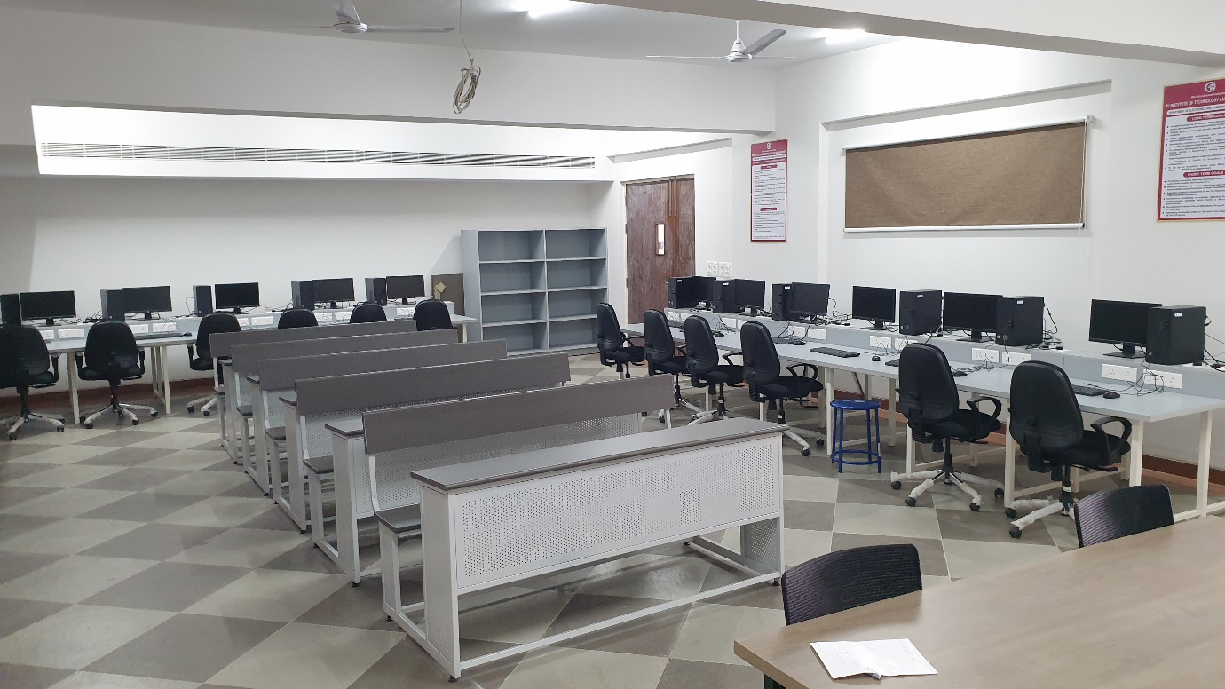
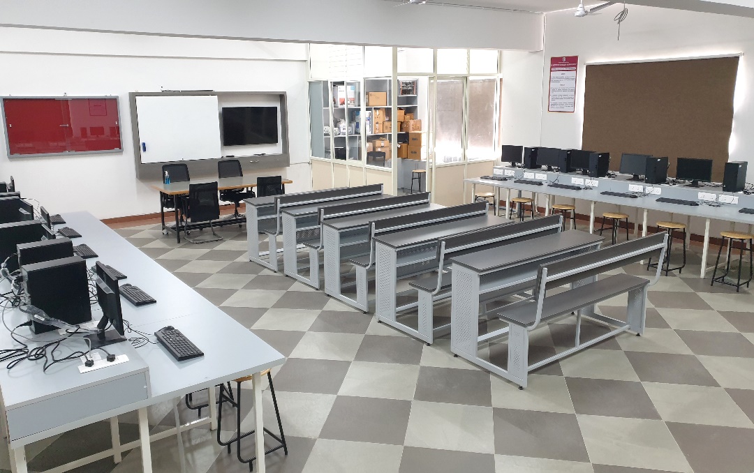
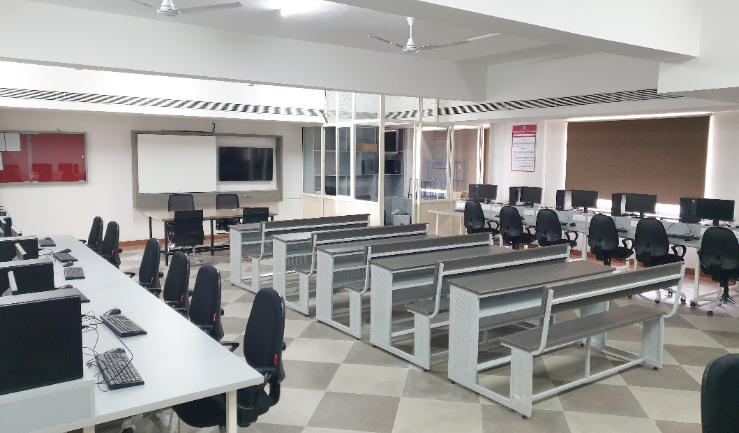
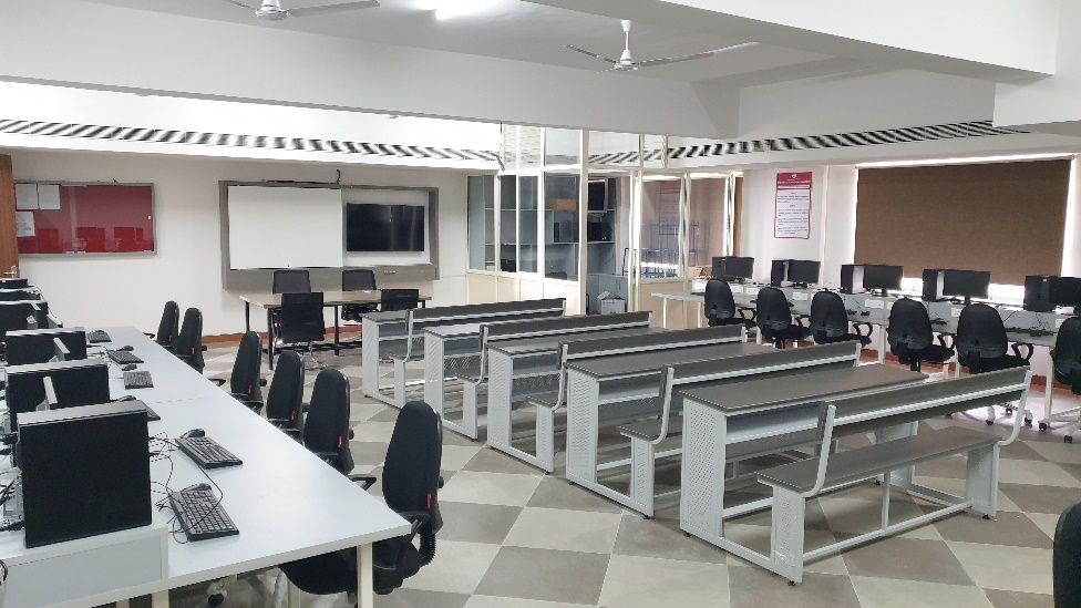
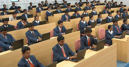
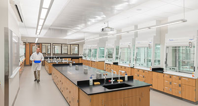
Computer-Aided Engineering Drawing (CAED) Lab is utilized by undergraduate students for software-aided drafting of 2D drawings. CAED is a technique where engineering drawings are produced with computer assistance, serving as a graphical means of representing a drawing or design.
Engineering drawing is the global graphic language used by engineers and technologists. It involves the graphic representation of physical objects and their relationships, conveyed through drawings using straight and curved lines to denote shape, size, and specifications. Understanding the theory of projection, dimensioning, and conventions related to working drawings is crucial for professional efficiency.
CAED involves preparing drawings of objects on a computer screen, supporting various types of drawings across engineering and science fields. Mechanical or aeronautical engineering focuses on machine component drawings and layouts, civil engineering involves building plans and layouts, and electrical engineering deals with power distribution system layouts. In all engineering fields, computers are utilized for drawing and drafting, with CAED offering enhanced graphics capabilities allowing designers to conceptualize ideas, modify designs easily, perform animations, make design calculations, and use colors, fonts, and other aesthetic features.
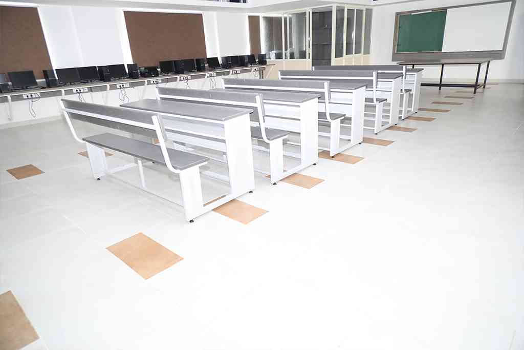
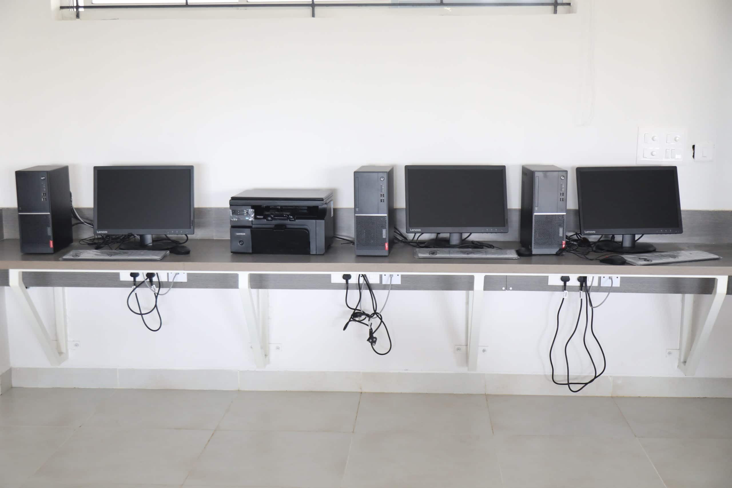
At RVITM, a licensed version of SolidWorks 2019 is used for drafting in the well-equipped CAED Lab, featuring sufficient systems and ICT tools in a centralized air-conditioned room.
Subject Code : BME302
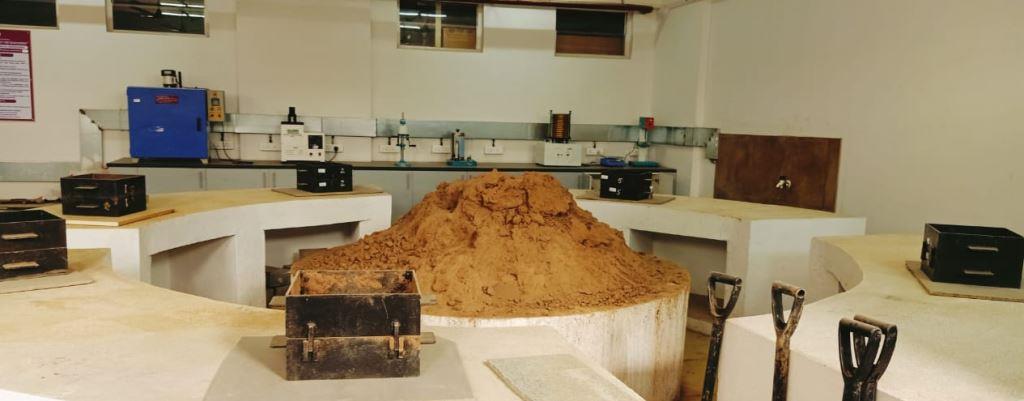
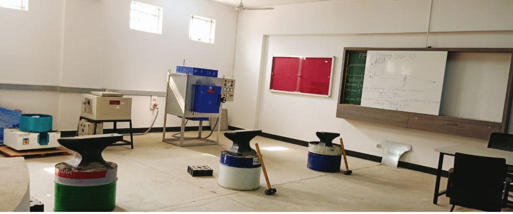
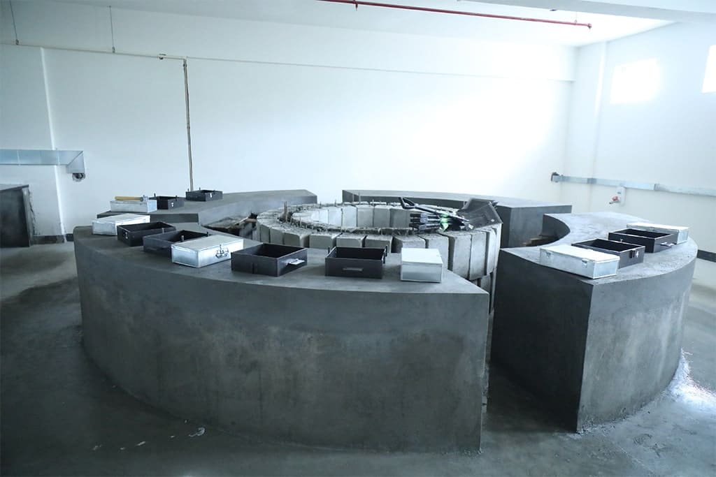
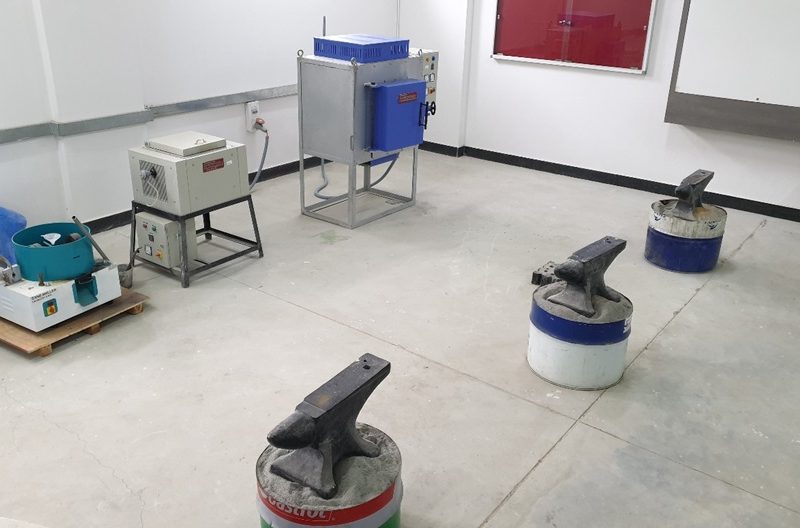
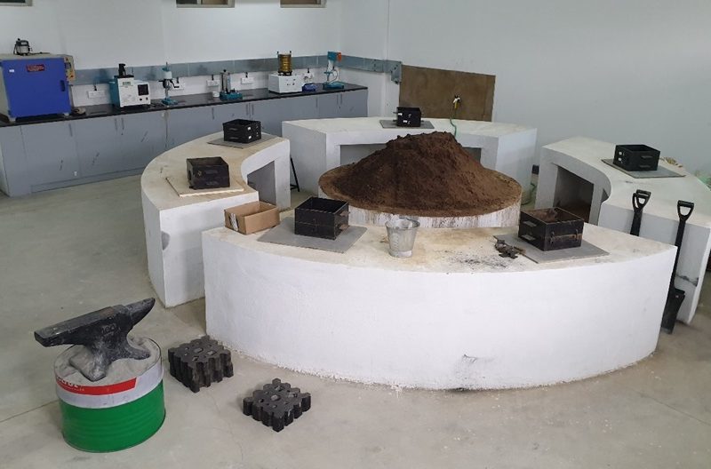
Foundry, Forging and Welding lab, is a part of Mechanical Engineering and it is equipped with state-of-the-art lab/research facilities viz. molten material preparation, sand testing equipment, various casting, forging equipment’s and welding machines etc. Here, the students will be working on various processes involved in casting and forging operations and learn the art of producing forged models like square rod, square bolt, hexagonal bolt etc. students will learn to make mould cavity with use for patterns namely single piece pattern and split piece pattern for casting using moulding sand. Then, students will be testing the strength of the moulding sand such as tensile strength, compressive strength, mould hardness, core hardness, permeability test, moisture content test etc. In this lab students will also be trained to do arc welding operations making different joints such as lap joint, butt joint, corner joint etc. Lab is provided with proper ventilation, space and sufficient lighting.
Subject Code : BME303
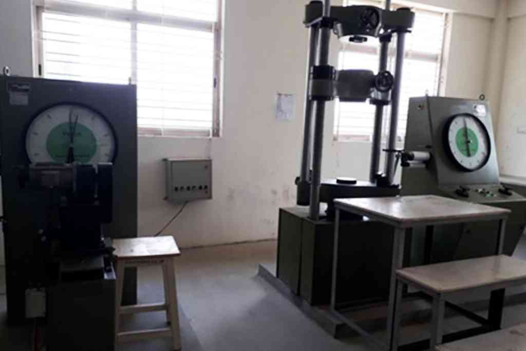
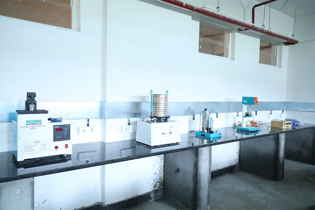
Material Testing Laboratory is designed to help students practically understand the characteristics and behaviours of various materials, such as metals, ceramics, plastics, and more. All students will learn to prepare samples and characterise the materials based on their performance (microstructure, the volume of a fraction of phases, and grain size). In addition, students will learn material failure modes and the different loads causing failure.
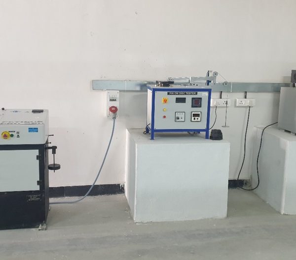
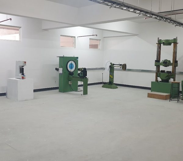
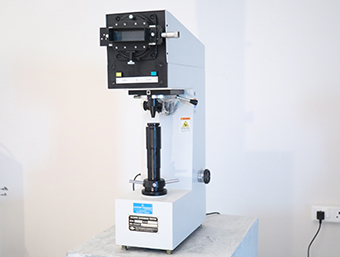
The important equipment in the lab includes a Metallurgical Microscope, Brinell Hardness Tester, Vickers Hardness Tester, Ultrasonic Flaw Detector, Electronic Universal Testing Machine, Torsion Testing Machine, Izod-charpy Impact Testing Machine, Wear Testing Machine, and Fatigue Testing Machine. The computerised UTM helps students to plot the graph digitally during the experiment.
Subject Code : BMEL305
Introduction to Modelling and Design for Manufacturing Laboratory is used by UG students for software aided drafting of machine parts and assembly drawings. This involves study of conventions in drawings that are widely adopted in engineering practice.
Introduction to Modelling and Design for Manufacturing is representation of a machine component or machine by lines according to certain set rules. A machine drawing generally gives all the external and internal details of the machine component from which it can be manufactured. Machine part is presented through a number of orthographic views, so that the size and shape of the component is fully understood. Part drawings and Assembly drawings belong to machine drawing. Part drawing is a detailed drawing of a component to facilitate its manufacture. A drawing that shows the various parts of a machine in their correct working locations is an assembly drawing.
The machining symbols, tolerances, bill of material, etc. are specified on the drawing. GD&T, short for Geometric Dimensioning and Tolerancing is used to define the nominal geometry of parts and assemblies, to define the allowable variation in form and possible size of individual features, and to define the allowable variation between features. GD&T uses a symbolic language on engineering drawings and computer-generated three-dimensional solid models that explicitly describe nominal geometry and its allowable variation.
Machine drawing lab facilitates the application of software for drafting machine parts and assembly of machine parts, detailed sectional views. Licensed version of Solid works-2019 is used at RVITM for drafting. Lab is well equipped with sufficient systems and ICT tools in a centralized A/C room.
Subject Code : BME358A
Introduction to python Laboratory is used by UG Students. Python is an interpreter, object-oriented, high-level programming language with dynamic semantics. Its high-level built-in data structures, combined with dynamic typing and dynamic binding, make it very attractive for Rapid Application Development, as well as for use as a scripting or glue language to connect existing components together. Python’s simple, easy to learn syntax emphasizes readability and therefore reduces the cost of program maintenance. Python supports modules and packages, which encourages program modularity and code reuse. The Python interpreter and the extensive standard library are available in source or binary form without charge for all major platforms, and can be freely distributed.
Often, programmers fall in love with Python because of the increased productivity it provides. Since there is no compilation step, the edit-test-debug cycle is incredibly fast. Debugging Python programs is easy: a bug or bad input will never cause a segmentation fault. Instead, when the interpreter discovers an error, it raises an exception. When the program doesn’t catch the exception, the interpreter prints a stack trace. A source level debugger allows inspection of local and global variables, evaluation of arbitrary expressions, setting breakpoints, stepping through the code a line at a time, and so on. The debugger is written in Python itself, testifying to Python’s introspective power. On the other hand, often the quickest way to debug a program is to add a few print statements to the source: the fast edit-test-debug cycle makes this simple approach very effective.
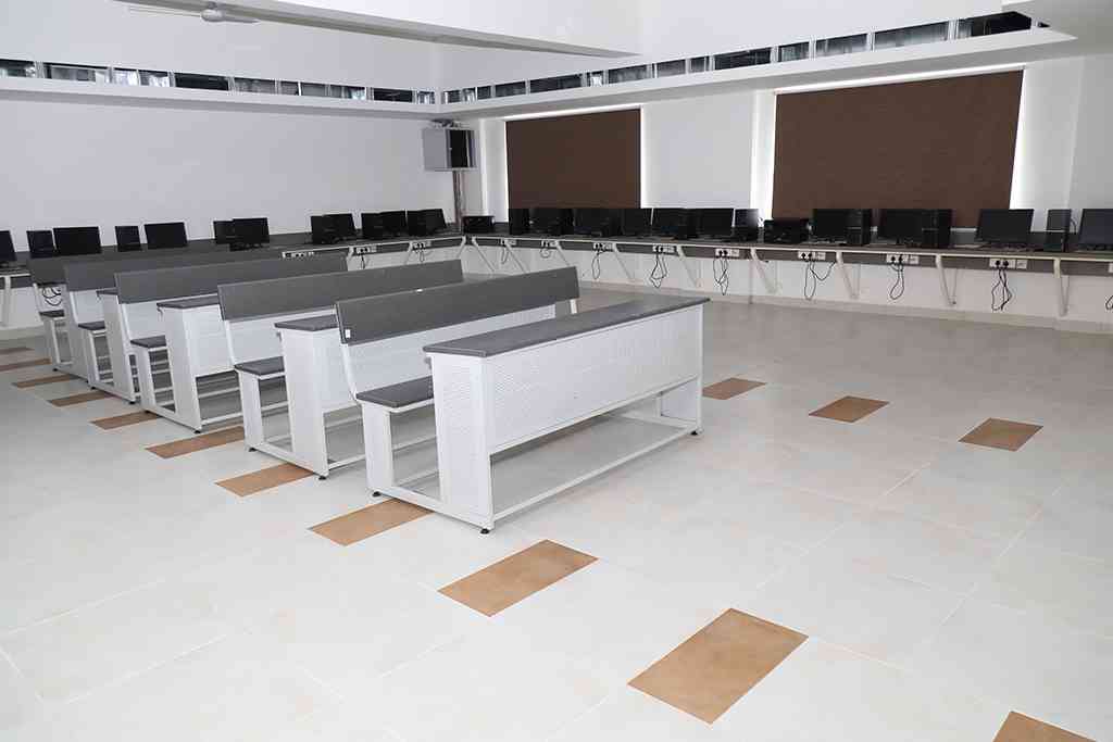
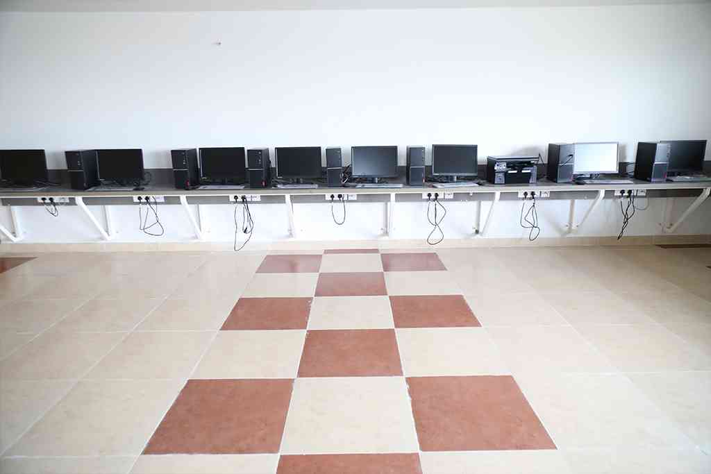
The Lab is well equipped with 20 number of high-performance computers. Software packages such as having IDLE (short for Integrated Development and Learning Environment) is an integrated development environment for Python, which has been bundled with the default implementation of the language campus-wide it is free license available from python website, and the same has been installed in the system.
Subject Code : BME402
Student use fitting tools to perform fitting operations and they will be provided insight into different machine tools, accessories, and attachments. Students will be trained with fitting and machining operations to enrich their practical skills.
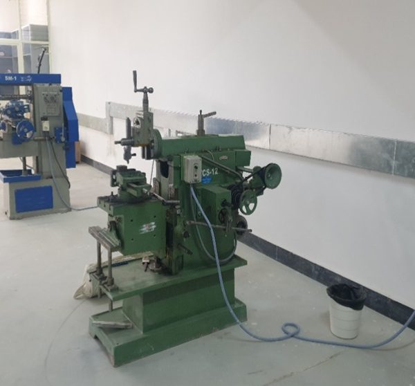
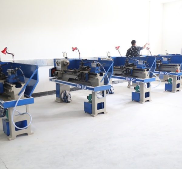
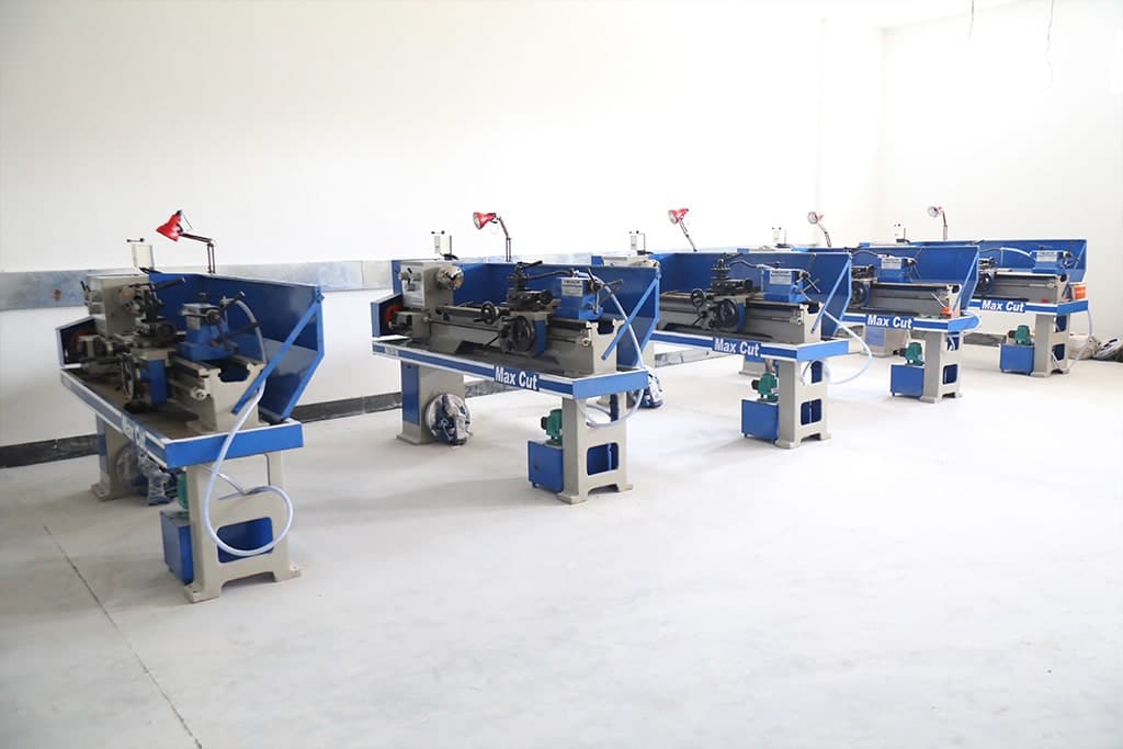
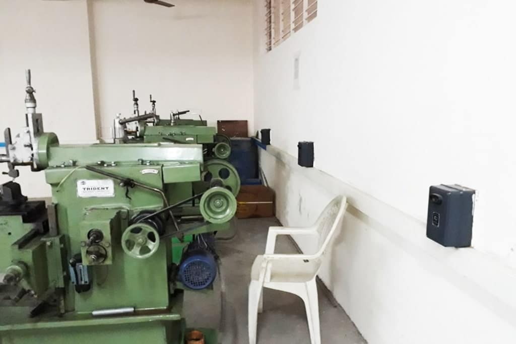
Machine shop laboratory will have major equipment such as Lathes, Shaping Machine, Universal Milling Machine, Bench Grinder, Power Hack Saw, and Radial Drilling Machine.
Lathe: Lathe machines are used widely in all mechanical industries and workshops to carry out various operations on the mechanical parts. Turning, step turning, Knurling, thread cutting, center drilling, and cutting are very common operations performed on the mechanical parts. The main function of Lathe machine is to remove excess material in the form of chips by rotating the work piece against a stationary cutting tool. This is accomplished by holding the work securely and rigidly on the machine and then turning it against cutting tool which will remove metal from the work. To cut the material properly the tool should be harder than the material of the work piece, should be rigidly held on the machine and should be fed or progress in a definite way relative to the work.
Following operations can be performed by using lathe machine for fabrication purpose i.e Turning, facing, grooving, parting, threading, drilling, taper turning, boring, knurling, and tapping.
Milling: A milling machine is a machine tool that removes metal as the work is fed against a rotating multipoint cutter. The milling cutter rotates at high speed and it removes metal at a very fast rate with the help of multiple cutting edges. One or more number of cutters can be mounted simultaneously on the arbor of the milling machine. This is the reason that a milling machine finds a wide application in production work. Milling machine is used for machining flat surfaces, contoured surfaces, surfaces of revolution, external and internal threads, and helical surfaces of various cross-sections.
Following operations can be performed by using Milling machine for fabrication purpose i.e
Plain Milling Operation, Face Milling Operation, Side Milling Operation, Straddle Milling Operation, Angular Milling Operation, Gang Milling Operation, Form Milling Operation and Gear Milling
Drilling: The drilling process is an important process in industry because it is used to drill holes in metal, wood, and other materials. The drilling machine uses a drilling tool with a cutting edge at its tip. The cutting tool is fixed in the drilling machine through the taper of the chuck (sleeve), and rotates at a constant speed and is fed into the work piece.
Following operations can be performed by using Drilling machine for fabrication purpose. i.e. Drilling, reaming, lapping, boring, counter-boring, counter-sinking, Spot facing, and tapping
Shaper: A single point cutting tool will be used in shaper machine tools. During the forward stroke of the tool, job will be machined and during the backward stroke of the tool, the tool will be idling. To achieve this, the cutting tools are mounted over an arrangement called clapper box. The mechanism used in Shaper Machine is Whitworth Quick Return Mechanism.
Following operations can be performed by using shaper machine for fabrication purpose i.e. Machining horizontal surface, Vertical surfaces, Angular surfaces, Cutting slots, grooves, and keyways.
Subject Code : BME403
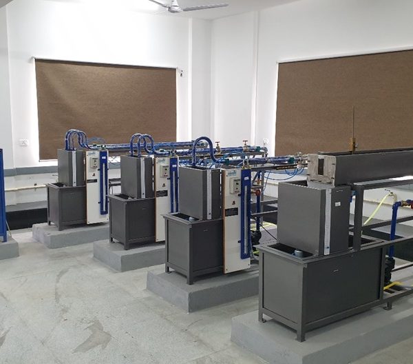
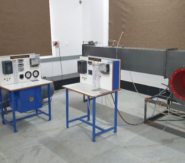
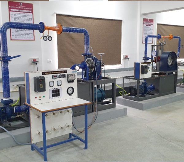
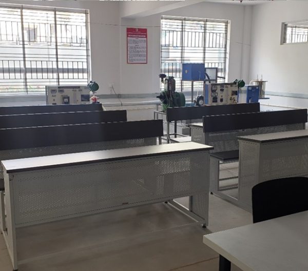
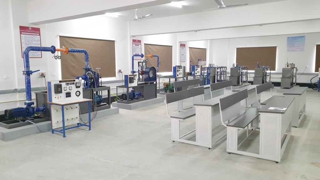
Fluid mechanics is that the branch of engineering. Science which deals with the behavior of the fluids at rest as well as in motion. In general, the scope of fluid mechanics is very wide which includes the study of all gases and liquids. Fluid mechanics deals with the analysis and methods to solve many engineering problems involving liquid flow, such as flow through pipes or channels, storage dams, pumps and water turbines, hydraulically operated machines such as lift, crane, press etc. Hence it is essential for the engineering students of Civil, Mechanical, and allied branches of engineering to understand the theoretical and practical aspects of fluid mechanics
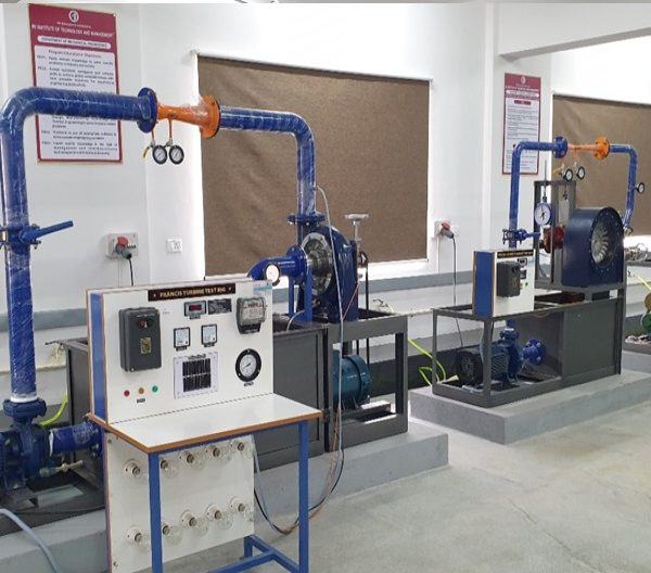
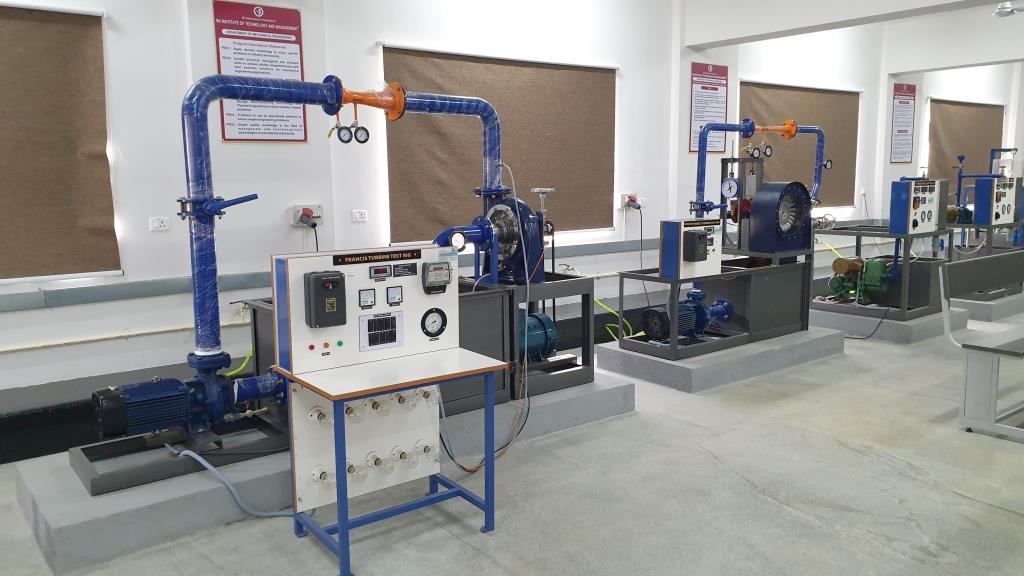
This laboratory is run in conjunction with the theory course (Fluid Mechanics and Machinery Lab). It is an introductory course where flow behavior, fluid forces and analysis tools are introduced. The goals of the experiments include understand the minor and major losses in flow though pipe and impact of jet experiment include determination of forces generated when fluid flow takes place over a solid object. The venturi meter, orificimeter and notch experiments will help in understanding the flow rate of fluids. The Pelton, Francis and Kaplan will demonstrate the working and analysis of hydraulic turbines. Similarly, the pump, air blower and compressor experimental set up gives information of working hydraulic machines under different conditions. This lab focuses on giving the user idea about the practical behavior of flow measuring devices and machines before performing operations on a real system.
Subject Code : BME404
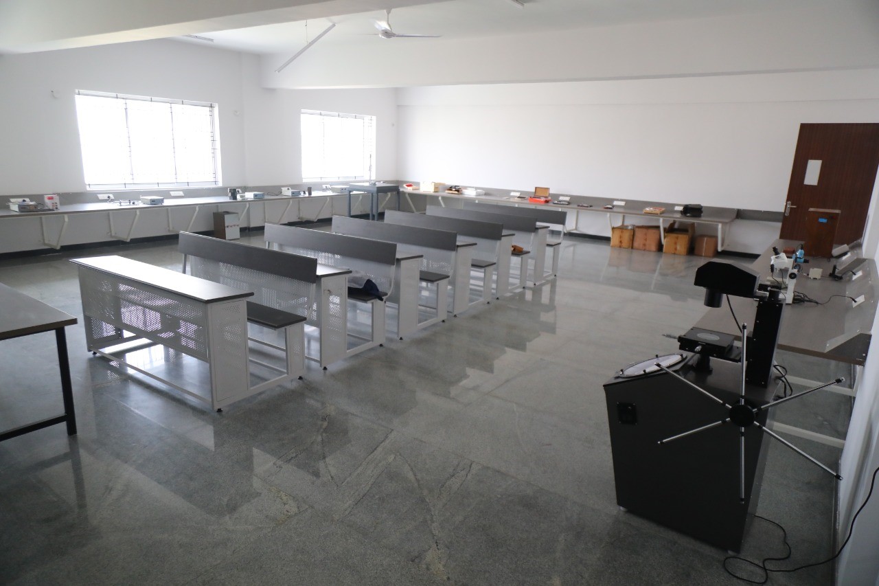
Mechanical Measurements and Metrology (MMM) laboratory is used by UG Students for measurements of various dimensions and tolerances of many components, and the procedures taught in the lectures are put into practice and expanded through practical trainings. Engineering metrology deals with the applications of measurement science in manufacturing processes. It provides a means of assessing the suitability of measuring instruments, their calibration, and the quality control of manufactured components. An organization should strive towards a zero-defect regime in order to survive in a highly competitive market. Ensuring this aspect of manufacturing is the responsibility of a quality control engineer, who must be completely familiar with the basics of measurement, standards and systems of measurement, tolerances, measuring instruments, and their limitations.
The MMM lab is equipped with a number of sophisticated equipment’s, for calibration, and for dimension measurement experiments to measure angular, linear measurements and tolerances. Furthermore, calibration of micrometre, slide callipers and other similar gauges. Several optical instruments for measuring linear and angular dimensions. Calibration of pressure, temperature, torque, stain gauge and load cells. Additionally, thread measurement by optical means and compound micrometre with 1, 2, 3 wire methods. Mitutoyo Instrument for measurement of surface roughness of various components.
Scope of Metrology
- Establishing units of measurement and their standards such as their establishment, reproduction, conservation, dissemination and quality assurance
- Measurements methods, execution and estimation of their accuracy.
- Measuring Instruments- Properties examined from the point of view of their intended purpose
- Observers capabilities with reference to making instruments, eg: readings of instrument indications
- Design manufacturing and testing of gauges of all kinds
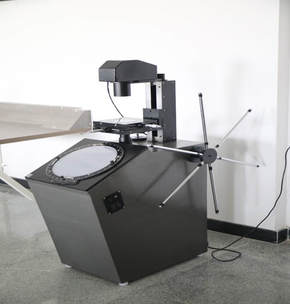
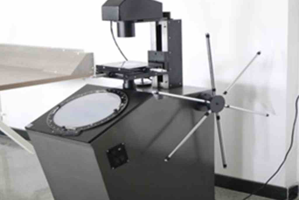
Mechanical measurements and Metrology Lab have various measurement and calibration equipments. The major measuring instruments available are Profile projector, Tool maker’s microscope, Floating carriage micrometer, Autocollimator, etc. The major calibration equipments are Sine bars with slip gauges, Thermocouple, Sine center, Strain gauge, Pressure gauge, etc.
Subject Code : BME456A
The AI & ML Lab is a platform where students engage in hands-on activities and projects related to Artificial Intelligence (AI) and Machine Learning (ML). In this lab, students delve into various aspects of AI and ML, including algorithms, models, and applications. Through practical experimentation, students develop both theoretical understanding and practical skills essential for working with intelligent systems.
The lab curriculum is carefully crafted to cover a broad spectrum of topics, catering to both beginners and seasoned enthusiasts. From classic algorithms like A* Search and AO* Search to advanced concepts such as neural networks and Bayesian networks, students traverse the evolutionary landscape of AI and ML methodologies. Each experiment serves as a building block, fostering critical thinking, problem-solving prowess, and creativity essential for tackling complex challenges in AI and ML domains.
The AI & ML Lab offers mechanical engineering students the opportunity to enhance their problem-solving skills by integrating AI and ML techniques into mechanical systems design and analysis. Through this lab, students can explore how AI algorithms can optimize mechanical processes, predict failures, and improve overall system efficiency, preparing them for future roles where interdisciplinary knowledge is crucial for innovation in engineering.
At RVITM, Jupyter Notebooks a versatile tool for interactive coding and data exploration, is used in the AI & ML Lab for its simplicity and effectiveness.
Subject Code : 21ME52
Thermo fluid engineering deals with the performance of heat engines, refrigeration system and the turbomachines. The lab component consists of analysis and methods to solve many engineering problems involving performance of different heat engines, refrigeration and air conditioning systems and turbomachines both power generating and power absorbing which includes hydraulic turbomachines, centrifugal pumps, centrifugal blowers etc. Hence it is essential for the engineering students of Civil, Mechanical and allied branches of engineering to understand the theoretical and practical aspects of Thermo-fluids engineering.
This laboratory is run in conjunction with the theory course (Thermo-fluid engineering). The goals of the experiments include understand the hydraulic turbines like Pelton, Francis and Kaplan which will demonstrate the working and analysis of hydraulic turbines. Similarly, the pump, air blower and compressor experimental set up gives information of working hydraulic machines under different conditions. This lab focuses on giving the user idea about the practical behavior of flow measuring devices and machines before performing operations on a real system.
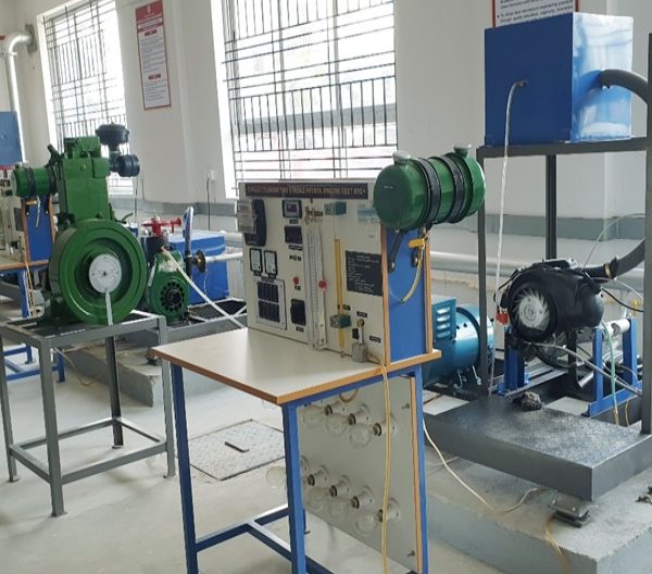
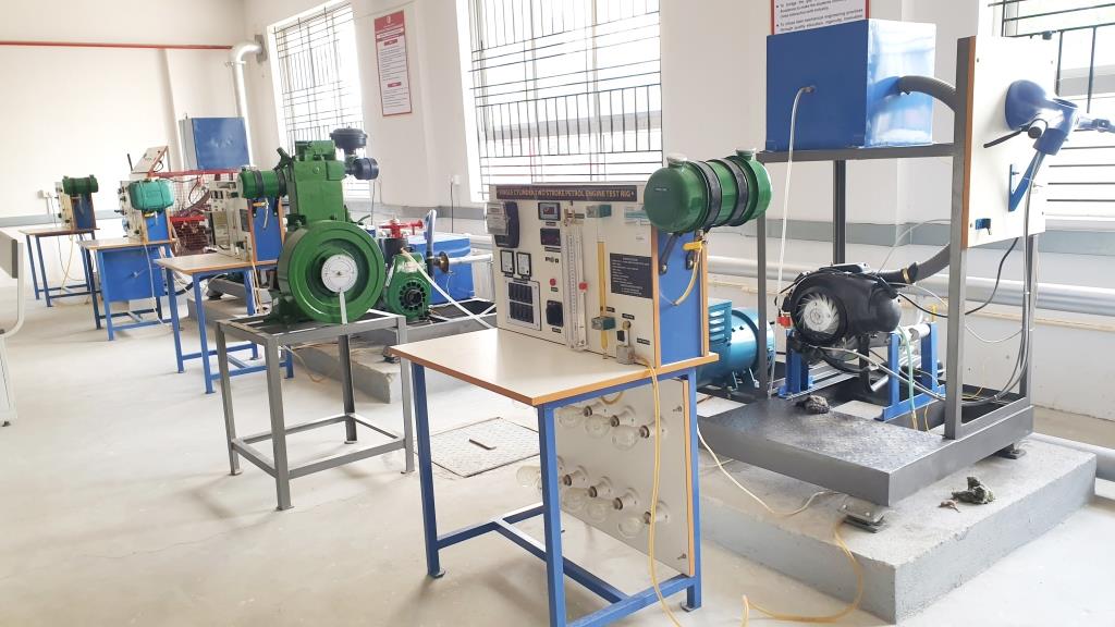
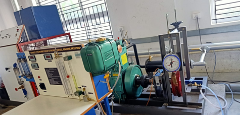
Energy Conversion (EC) laboratory provides the working operations of Internal Combustion (IC) Engines like Compression Ignition (CI) Engines and Spark Ignition (SI) Engines) and its applications. The Energy Conversion lab consists of Four Stroke (4S) Multi-Cylinder Petrol Engine (Morse Test), 4S Single Cylinder Petrol Engine with Variable Compression Ratio (VCR), 2S Single Cylinder Petrol Engine, 4S Single Cylinder Diesel Engine, Sections of 4S Diesel Engine, Petrol Engine. The fuel property measuring devices like Torsional Viscometer, Redwood Viscometer, Bomb Calorimeter, Boy’s Gas Calorimeter etc. This laboratory has exhaust gases analysis facilities like smoke meter and 5gas analysers.
At the end of the laboratory experiments, the students will be able to know about all the experiments of EC Laboratory and provide the practical knowledge on I.C Engines performance and emissions measurements and calorific value & viscosity of various sample oils.
Subject Code : 21ME53
Computer Aided Modelling and Analysis Laboratory is used by UG Students. The ANSYS program has many finite element analysis capabilities, ranging from a simple, linear, static analysis to a complex, nonlinear, transient dynamic analysis. The analysis guide manuals in the ANSYS documentation set describe specific procedures for performing analyses for different engineering disciplines.
A typical ANSYS analysis has three distinct steps:
- Build the model.
- Apply loads and obtain the solution.
- Review the results.
The finite element method is perhaps the most popular numerical technique for solving engineering problems. The finite element method is generally enough to handle any complex shape or geometry, any material properties, any boundary conditions and any loading conditions. In addition, it is an efficient design tool by which designer can perform parametric design studies by considering various design cases (different shapes, materials, loads etc.), analyses them and can choose the optimum design.
The Lab is well equipped with 20 number of high-performance computers. Software packages such as ANSYS having campus-wide license available from CADFEM India (P) Ltd., and the same has been installed in the system.
Subject Code : 21MEL55
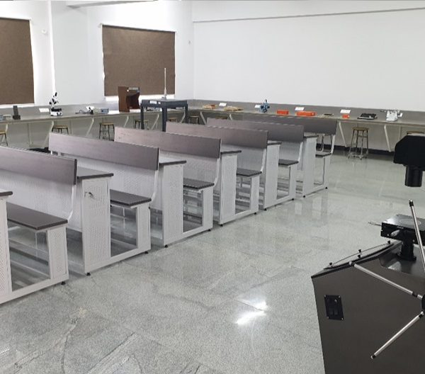
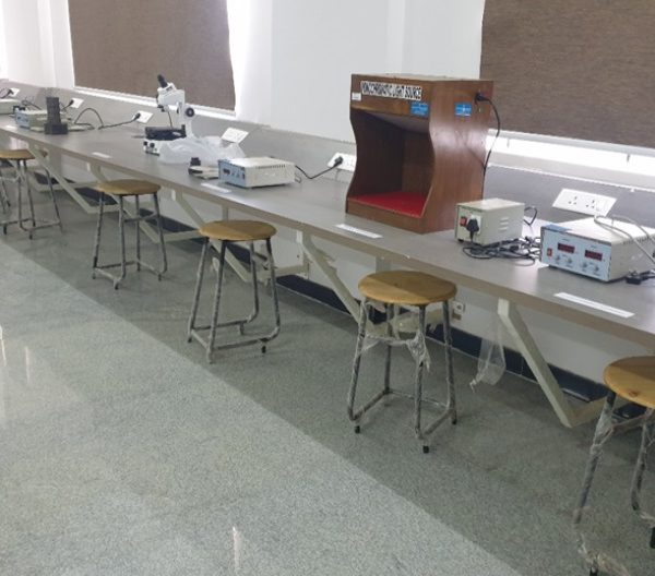
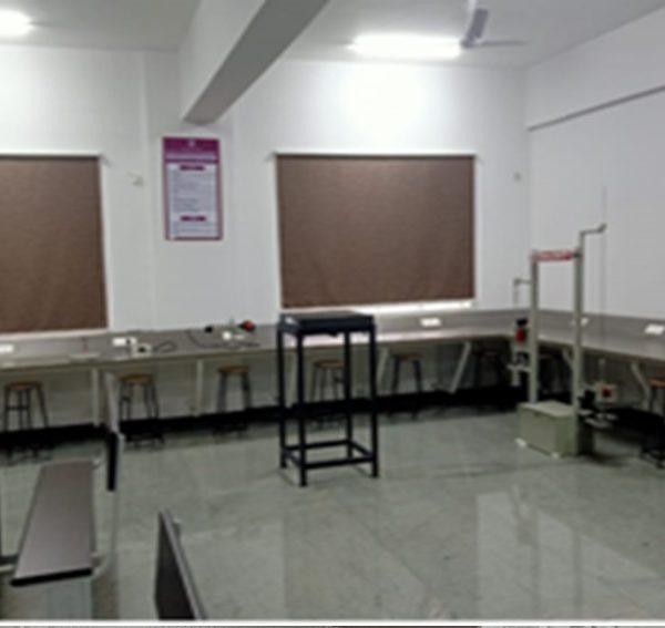
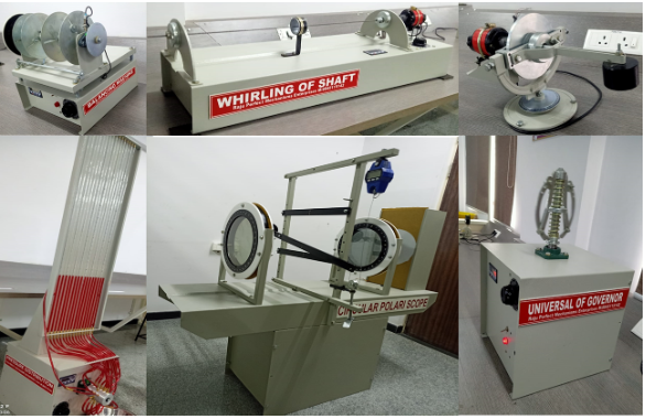
The Design Laboratory contributes to educate the undergraduate student as well as in the research areas in the field of Mechanical Design. The mission of Design lab is innovative mechanical component design, improve design quality, shorten design time, and enhance design education. This lab experiments validates the concepts of kinematic and dynamic theories of machine components under motion condition. Students can be able to validate and extend the theoretical knowledge into practical machine applications. The structural analysis laboratory section has been designed to facilitate the practical study of structural response of basic structural elements, namely, the beam, column, rigid and pin jointed frames.
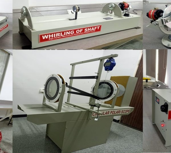
The Design Lab is containing 8 Equipment to conduction 10 experiments with highly standard. Experiment in the Design lab students can be able to Find the stiffness and critical damping of the system. Calculate the damping coefficient, logarithmic decrement, damping ratio, damping frequency and natural frequency of the system and Learn the effect of damping in forced vibration of a single degree of freedom due to forces. Students can able to get the knowledge on different types speed governors and strain gauges. By conducting Polariscope experiments for transparent materials students can understand the photo elastic principle is particularly suited for the analysis of stress distribution in flat models.
Subject Code : 21ME581
MATLAB is a powerful and widely used software tool in various engineering disciplines, including Mechanical Engineering. It is essential for tasks such as data analysis, numerical simulations, and visualization. MATLAB stands for “MATrix Laboratory.” It is a high-level programming environment designed for numerical computing, data analysis, and visualization. MATLAB provides a user-friendly interface and a vast array of functions and toolboxes, making it a versatile tool for engineers and scientists. In the context of Mechanical Engineering, MATLAB can be employed for a range of applications, including but not limited to:
- Data Analysis: MATLAB is used to process and analyze experimental data, such as stress-strain curves, temperature measurements, or sensor data from mechanical systems.
- Numerical Simulations: Engineers can create and solve complex mathematical models of mechanical systems, like finite element analysis (FEA) for structural analysis, computational fluid dynamics (CFD) for fluid flow simulations, and dynamic systems modeling.
- Optimization: MATLAB has optimization algorithms that can be used to find optimal solutions for design problems in mechanical engineering, such as optimizing the shape of a component or minimizing material usage.
- Signal Processing: MATLAB is essential for analyzing and processing signals from various mechanical systems, including vibration analysis and control systems.
- Visualizations: Engineers can create graphical representations of data and results, such as 2D and 3D plots, contour plots, and animations, to better understand and present their findings.
Subject Code : 21ME62
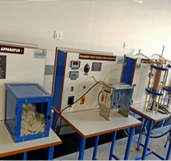
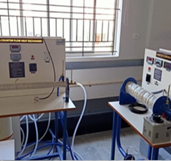
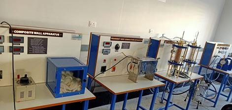
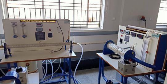
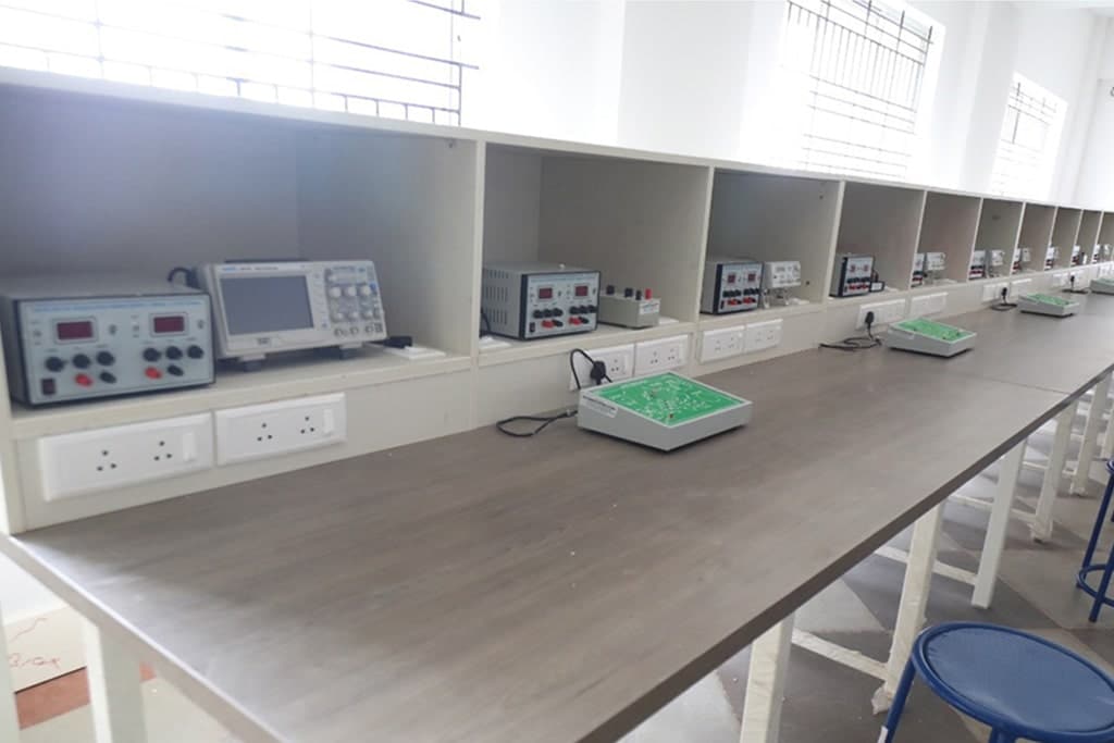
Heat Transfer laboratory provides fundamental and industrial knowledge about modes of heat transfer, like conduction, convection and radiation, and their applications. Heat Transfer Lab consists of the following equipment’s such as, natural and forced convention heat transfer set-ups, conduction and radiation heat transfer equipment’s etc. This lab also consisting refrigeration and air conditioning basic experimental set up to explain the fundamental concepts of air conditioning.
This laboratory will provide students with the necessary skills to conduct experiments on conduction and convection of heat; collect data, perform analysis and interpret results to draw valid conclusions through standard test procedures. This lab also helps to understand the various thermal properties and performance of radiation heat transfer, heat exchanger, vapour compression refrigerator and air conditioner.
Subject Code : 21MEL66
CNC Programming and 3D printing Lab is utilized by undergraduate students for software-aided manufacturing. A CNC Programming and CAM (Computer-Aided Manufacturing) lab is a specialized facility where students, engineers, and researchers can gain hands-on experience in CNC machining, programming, and CAM software. Such labs are essential for training individuals in modern manufacturing techniques and preparing them for careers in industries that rely on CNC technology.
A CNC Programming and CAM lab is a dynamic environment that bridges theory with practical application, enabling individuals to master the tools and techniques of modern CNC manufacturing. The lab’s resources and activities contribute to a well-rounded education in manufacturing technology and foster innovation in the field.
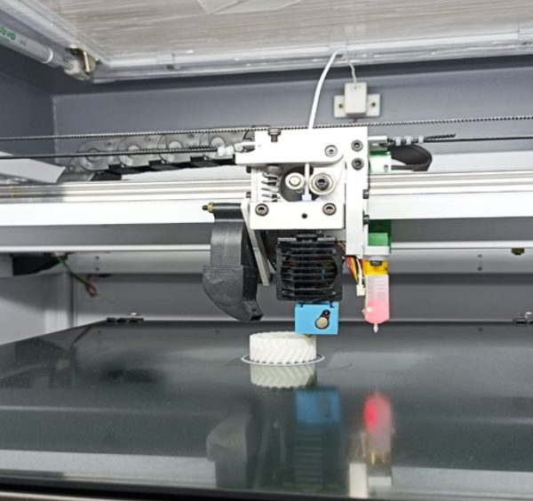
A 3D printing lab and a product development lab are both innovative spaces where ideas are brought to life through technology, creativity, and iterative design processes A 3D printing lab, also known as an additive manufacturing lab, is equipped with various types of 3D printers and related tools to create three-dimensional objects from digital models.
Fused Deposition Modeling (FDM) Printers: These printers extrude thermoplastic filaments (e.g., PLA, ABS) layer by layer to build objects. FDM printers are popular for rapid prototyping and functional part production.
3D printing lab serves as a hub for innovation, education, and research, empowering students to explore the possibilities of additive manufacturing and harness its potential to revolutionize product development and manufacturing processes across various industries.
The Lab is well equipped with 20 number of high-performance computers with Software packages such as CNC Train –Mill and Turn from MTAB Technology Center P Ltd. And lab having Pratham 3.0, FDM 3D printer which was supplied by LENIVA CAD Solution,
Activities and Learning Objectives:
CNC Programming: Students learn how to write G-code programs to control CNC machines. This includes understanding toolpath generation, specifying machining parameters, and optimizing cutting strategies.
CAM Software Operation: Students gain proficiency in using CAM software to generate toolpaths from CAD models. They learn how to set up machining operations, select cutting tools, and simulate the machining process.
Prototyping and Product Development: Iterative design and rapid prototyping to visualize concepts, test functionality, and refine product designs before moving to mass production.

